Pre-Stack Reverse-Time Depth-Migration
reflection seismics recordings. Here pre-stack migration is considered
where shot-records are individually migrated and subsequently stacked.
Pre-stack reverse-time depth-migration is based on full-wave
seismic modelling on a numerical grid. It is mainly made up of two
processes:
1. Seismic forward modelling of a wave field originating from the source
position
2. Reverse-time modelling of the shot-record, where the time samples are
fed into the modelling scheme at their respective positions as
boundary conditions in time-reversed order, i.e., last time sample first
In both processes at any subsurface grid node time histories
(seismograms) are generated and stored. Then for any grid node the two
seismograms of the two processes are correlated, i.e. a scalar product
is performed. The resulting amplitude value is then attributed to the
respective subsurface location.
The idea behind this procedure is that sufficiently strong correlation
amplitudes can only be expected at subsurface locations where a reflection
occurs.
Occurrence of a reflection at a certain location means that there is a
down-going wave field from the source side and an up-going wave field
towards the receivers at the same time.
This procedure is valid under the assumption that only first order reflections
are present in the seismograms, which is not exactly the case in reality.
The direct wave (first arrival) and head waves therefore need to be
muted in the records prior to feeding them into the reverse modelling.
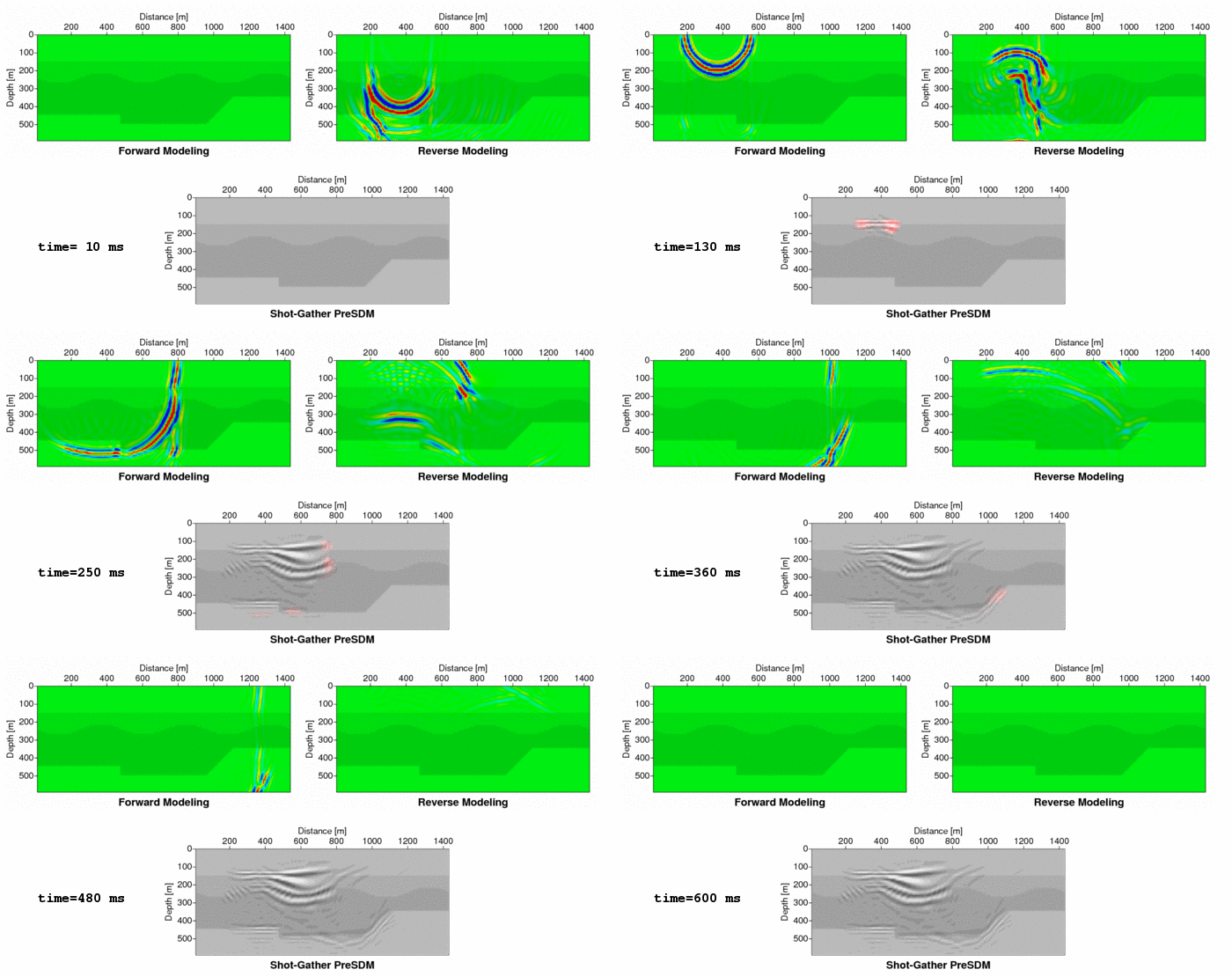
In the animation three panels are on display:
In the top row evolution of the wave field of both, the forward and the
reverse-time modelling is shown (also see time display).
Below, the correlation result (partial image) is shown as a function of time.
The red coloured portions in the partial image denote the correlation result
of the respective time instance.
The subsurface structure to be resolved consists of four layers separated
by three interfaces of different shapes (plane, sinusoidal and
step/ramp-like). The three panels are overlain by the velocity model of
the structure. This allows to interpret changes in the wave fields and
to verify that the interfaces were reasonably imaged.
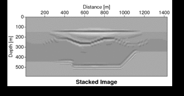
For the final image the partial images of 15 shots from
source positions which had a spacing of 5 grid nodes in the horizontal
direction were stacked.
In this small 2D example the numerical modelling scheme uses the acoustic
one-way wave equation in order to avoid artifacts due to multiple
reflections between interfaces. The modelling algorithm is based on the
Fourier method.


Model parameters
| nx | 143 |
| nz | 60 |
| delta_x | 10 m |
| delta_z | 10 m |
| delta_t | 0.5 ms |
| t_max | 0.6 s |
| f_max | 100 Hz |
| vp | 2000, 2500, 3000, 2000 m/s |
References:
Baysal, E., Kosloff, D., and Sherwood, J.W.C., 1983, Reverse time migration: Geophysics, 48, 1514-1524
Chang, W. F., and McMechan, G. A., 1986, Reverse-time migration of offset vertical seismic profiling data using the excitation-time imaging condition: Geophysics, 51, 67-84.
Gerard T. Schuster, 2002, Reverse-Time Migration = Generalized Diffraction Stack Migration: Expanded Abstracts SEG Meeting
